

wrs
-
Content Count
347 -
Joined
-
Last visited
-
Days Won
2
Posts posted by wrs
-
-
Nice!!
I think that would be worthwhile.
When you say no interior do you mean completely stripped as in no dashboard too? At the very least it would show where the water can track from-to...
-
I've been chasing water leaks for the last few weeks. I've identified all but one of the sources. The last leak has me a bit baffled though so hopefully someone here will know this one. It's in the front left corner of the passenger footwell up against the firewall.
The photo below shows where the water reveals itself for the first time. The yellow circle encloses the wet area where the water comes out. The water appears to be coming out from behind the black sound padding and runs down the cable loom marked, goes behind the plastic shield and ends up on the floor. The small ledge where the sound padding finishes is also wet. Is this similar to the A-Pillar leak I've seen mentioned on many sites or something else?
The water has been coming in over the last few days while it's been raining. I've tried to get water to enter by running the hose on the sunroof, down the windscreen and onto the shield below the windscreen but cannot get the leak to show. It doesn't appear to be leaking through the door or door seal.

I have to take the dashboard out soon to replace the heater and want to install new carpet at the same time but have to have all the leaks fixed prior.
Any ideas where to look?
-
Thanks - had already considered that. I was counting on this as part of the control. I'm only wrapping a temperature limit control loop round the heater core temperature so stop it hitting 200'C+.
It's also why I'm switching the main control current with mosfets as a relay would wear out quite quickly being modulated.
Inside the heater there are 2 temperature sensors, one for each side. Looking at the guts of the control board these sensors appear to feed back the air temperature after the heater cores to the uP. I suspect the water solenoids are modulated to control the air temperature coming out of the heater to match the user control setpoint. My only concern is if they've implemented a PI or PID loop to control the solenoids based on the time constant of the heater energy/mass which I stuff up by putting in a heater core with a much faster response due to much smaller mass. Worst case I can try to emulate the original heater time constant in software...
That was also another reason to do the control loops in software vs opamps and comparators - easy to change.
-
Protel99se - been using the Protel products for 25+ years. Haven't bothered to update it as it does everything I need it to do. I've even done an A3 sized 8-layer board and it coped ok.
I did a couple of load checks on the heater element last night and it appear to initially have a negative temperature coefficient. I was expecting this but it almost looks like the minimum resistance is going to be about where my operating point is. The label on the packaging says the Curie temperature is around 200'C which means it likely to be negative up to just before then. I didn't have enough current available from my power supply to see what happens up round 14V. I've also designed the control round using semiconductor temperature sensors so 125'C max on the element. If I change to PT100's or similar I could let the element get hotter.
The net result might be more power than expected. That wouldn't be too bad as long as the current isn't too high.
The PCB is almost complete at the manufacturer (up to silk-screen stage) - may even ship today since it's only 1:30pm in Hong Kong!!
-
Manual conversion is good but you'll also need to change the diff or it will rev too high...
-
Hi Gus,
Seems there's some similarities between your problem and one I had. In my case I actually never solved it but I think I found out what it was right before I did an engine upgrade and manual convertion. My issue started at 125,000km and I followed a very similar path to try to fix it to you (including replacing / reconditioning the driveshaft - twice). Mine shuddered at 25km/h and again a little less at 50km/h and then from about 96km/h it started to vibrate - kind of a droning noise. I did find replacing the CSB with a new one with fresher stiffer rubber helped for a while but never fixed it, just helped mask it. I did 200,000km with it in this state...
Although I never proved it conclusively it appeared to be Jatco trans causing the problem. How I found it was to disconnect the trans from the driveshaft, start the car and watch the engine & gearbox from under the car while on a hoist. When in the same gear and RPM as 25km/h when driving (no speedo with the driveshaft disconnected) the whole engine and gearbox began to shake slightly with the gearbox tail section shaking quite a lot. With the driveshaft connected this would have caused the CSB section to shake as well and under heavy load would really move around. Mine never actually made a thudding noise but shuddered much worse under heavy acceleration.
We then reconnected the driveshaft and took out the exhaust heatshield so we could watch the driveshaft. At 25km/h it started to shake with the engine. We then wedged a couple of 4x2's between the trans tail section and he trans tunnel and the driveshaft stopped shaking. The gearbox appeared to be the cause of the shaking but it could have been coming from somewhere else.
I no longer have the problem due to manual trans.
Maybe something is out of balance in the trans? Maybe there is also one cylinder down causing torque ripple in the drivetrain - not sure if this could do it.
I came to the conclusion the issue wasn't in the drive train (since I'd replaced most of it).
-
A little more progress today:
Heater PCB Designed and ordered from China.

My alternator appears to be 140A so should not need to be upgraded.

New heater cores arrived today

Will start fitting up the cores tomorrow.
-
Do you have a Jatco trans?
Is it worse under heavy acceleration or does the drive-train torque not matter?
At 20km/h does it also shudder?
-
 1
1
-
-
The new cables are in.
New Hex Crimp Join + 2 x 6mm² Cables + Glue-Lined Heatshrink. The cables are protected by some 16mm beta-flex tubing.

Bung Holes Sealed + Surface Rust Killed & Painted

Cover Refitted

I've started work on the control board. The circuit is attached as a PDF. Decided to use a small 8 bit Arduino based microcontroller as it makes the board really simple. I'll complete the PCB design in the next couple of days then order from China - should be here by next weekend.
-
Converting my heater over to electric started from the failure of the central locking system and electric windows on my coupe. During the diagnostics for the electrics I discovered 3 water leaks contributing to the water under the carpet that corroded out the +12V junction under the passenger seat.
1. One of the floor bungs had popped out allowing road water to enter when driving in the wet.
2. The seal between the heater and firewall had failed + the drain for the air entry into the heater was blocked.
3. My heater core is leaking (but only just).
Because the heater solenoids are also stuffed with one side is stuck on hot and the other cold I decided rather than try to fix / replace everything why not convert the heater to electric. The BMW solenoid spare part is around $650+GST... My battery is in the boot with the main 70mm² cable running under the drivers seat. Tomorrow I'm going to cut this cable and re-join it with a barrel hex-crimp + fit 2 x 6mm² cables in prior to crimping. These 2 cables will be double sleeved to make sure there's no chance of a short to chassis. They will supply the bulk power to 2 new electric heater elements.
I purchased a complete second hand heater from the wreckers. I also used this as an excuse to pull the dashboard out of the donor car so I could see how it's done and what old brittle plastic breaks in the process. It's remarkably easy, just time consuming. I've now stripped down the heater unit and removed the air-conditioning core and the heater core. My air-conditioning compressor died about 10 years ago and de-gassed itself in the process so I removed it back then - not worth fixing. When I did the engine upgrade a while ago I ripped out all the remaining air-conditioning garbage from the front of the car - got rid of around 60kg.
I've purchased 2 x 300W ceramic PTC heaters from Ebay. These should draw about 21-23A at 14V since they operate almost like constant power devices. This means a total load of 42-46A on the alternator - hopefully it can cope. If not then I'll upgrade it. The new heaters should arrive later this week.
I'm going to fit the new heater elements to an aluminum plate that will be glued into the position the old heater core lived. There's 3 openings that also need to be blocked up; where the air-conditioning pipes entered, where the coolant pipes entered through the firewall and where the coolant pipes enter the heater box.
Now for the controls for the heater elements. The heater element will not be allowed to run unless the engine is running and the battery voltage is above 13.5V. This will turn on 2 relays that supply 13.5-14.4V to one end of the heater elements. The heater element on-off control will use the original water solenoid control signals. This will operate the left and right heater elements independently just like it used to. I'll construct a simple dual switch using mosfets which is enabled by the heater solenoid signals. There will be a temperature sensor on each heater element to limit the element to 95'C (similar to coolant temperature). The mosfets will switch on and off to keep the elements at 95'C. There will be a secondary sensor on each element to switch it off if it reaches 110'C in case the primary fails (drop out the main relays). The mosfets will pull the other end of the heater element to ground.
The climate control system is expecting the heater core to run at about 90-95'C (coolant temperature) so I'm hoping setting the elements to this temperature means the temperature regulation will still work in a similar way to original. I suspect the 300W heater elements won't get to full temperature most of the time though. The airflow will likely be much higher than required to keep them below 95'C. It's also likely it won't create anywhere as much heat as the old heater core could have as 600W is not much power. It will be instant heat though as soon as the engine is running and it will still be enough to heat the small space - it just might take a minute or two longer to warm up.
I'll take a bunch of photo's once the heater elements arrive and start fitting everything to the donor heater case. I'll also include the fairly basic circuit for the control of the elements once this is knocked together.
Given there's a lot of E36 out there with failed heater solenoids and heater cores just waiting to leak (or already leaking) this mod might appeal to some people. The cost in dollars to do the conversion is relatively minor. The time is not. I'm guessing around 4 days to build the new heater, strip everything out of the car, bypass the heater pipework, fit the new heater and put everything back together.
My car is already stripped out except for the dashboard - no seats (except drivers seat), carpet, glovebox or console - about a days work so far to strip everything out, clean it up and rust-kill a couple of surface rust areas that have been sitting wet for a while.
-
3
-
-
After looking at the Integrated Climate Regulation (IHKR) wiring diagram I can see changing to an electric heater is even easier than I'd thought. I can use the original water valve assembly control wires to switch the left and right electric heaters on and off. When switched on I'm going to use simple temperature control on the heater cores. The original water heater core would have run at around 90-95'C so I'll simply regulate the electric core to run at about 93'C using a thermistor & comparitor to switch a mosfet on and off - no need for PWM. Then the heat regulation should be fairly similar. I suspect the electric heater won't actually get up to 93'C very often as the airflow past it will likely keep it pretty cool. The original water heater core would be able to deliver much more than 300W to each side of the car...
I'll switch the main 12V supply to the heater cores with relays as well to give a double level of protection. Then I can add a second set of thermistors for over-temperature detection to switch off the relays - don't want a fire if anything goes wrong. The relays will also switch off with the ignition and the original water valve control.
-
Today I ordered the new seal from BMW - 2 weeks ex Germany $85.
I've also found a second hand heater unit at the wreckers I'm going to take out on Saturday - good training for taking out my dash. Once I have the second-hand unit I'm going to take it apart to remove the heater core and air-con core. I'll replace the original heater core with 2 x 300W ceramic electric cores and make a PWM controller to regulate the power. I'll check the state of the motor bearing at the same time and hopefully only need to lube them a bit. With the carpet currently out of the car it will be easy to tap into the main 12V wire to the battery for a high-current power source for the heaters. It passes under the drivers footwell area with a good solid cover. It will be easy to cut the cable and join with a Utilux barrel-crimp with additional wires added, then hex-crimped with a hydraulic crimper. Two layers of glue-linded heatshrink should ensure the insulation never wears through + will make the join water-tight. Will need to check the alternator is good for 2 x 21.5A continuous. For the heater control I'm going to add voltage detection so the battery has to be over 13.4V before the heater can be active (car started and alternator charging)... I'll have to try to figure out how the temperature regulation works on the existing system and link this to the PWM control for variable power to the heaters.
My heater control valves failed a while ago and they're nasty to repair and very expensive to replace. I'll just loop the in-pipe to the out-pipe and remove the valve completely - won't be needed with the electric heaters. Going electric will also mean instant heat as soon as the engine is running. It also means I'll never have to worry about the heater core leaking in the future.
-
Update:
We finally got some rain yesterday and I still have a leak. It's coming from the heater seal. I checked the scuttle drain and this was mostly blocked with only a very slow drip. It's now unblocked and flows freely but when I slowly pour water into the scuttle bay there is still a leak into the cabin from the heater. It's a big leak on the passenger side (left) and very small on the drivers side (right).
This means the seal from the scuttle bay round the heater has failed - bugger!!!
I really don't want to have to take the dash out - is there any other option to fix the seal? Can I poo some sealant round the heater?
However, I'm already half-way there as I took the carpet out yesterday so I could see where any leak(s) were coming from. So far it looks like just the heater. To get the carpet out I had to remove everything except the dash... With the carpet out I found quite a lot more surface rust + the black goo was delaminating off the painted steel with water trapped behind it. I removed the black stuff and dried everything out. Will rust-kill before the carpet goes back in. The old carpet was still quite saoked in a lot of places even though I'd had it lifted for the last week and a half. Since I have a new carpet to fit I mostly cut the old carpet out.
If I take the dash and heater out to replace the heater seal (and o-rings) is there anything else recommended to do - was going to lube the fan bearings as they've been squeaking after about 30 minutes operation for several years now. Maybe replace the filter too? My aircon died a few years back too so that's already degassed (degassed itself when the compressor blew + removed all the front radiator, compressor + filter etc when doing the engine swap - it was a lot of weight!!). It will also allow much easier access to replace the carpet (got a second hand carpet in much better condition to put back in - no mould, is not smelly and is already dry).
-
Problem Solved
It was the +12V red/green wire junction under the front passenger foot-well area. The glue holding in one of the bungs to the underside of the car had let go and the bung had popped in so water could get in when driving in wet weather. The whole area under the carpet was flooded and the +12V junction had one wire corroded off and signs of corrosion on 2 others. I cut the junction out, twisted the wires together and crimped them + covered in glue-lined heatshrink. Everything worked fine after that.
I then glued the bung back in with marine urethane. I've left the passenger seat out and the carpet up to dry out. I'll also be able to see if it still leaks when it rains - it's bound to rain this week sometime...
Of course, I only found this after taking the door apart first... The give-away was no 12V on any wire in the door. One wire had 1.6V on it - likely the corrosion conducting a tiny amount.
I also found broken wires in the boot loom and fixed these too but it wasn't the cause of the problem. I've seen a lot of instructions how to fix this any may say to cut the sheath covering the wires. You don't have to do this - it's silicone covered fibreglass sleeving and it bunched up really well. All you have to do is pop the bung out of the boot end, unclip the sheath from all the plastic clips on the boot mechanism and slide the sheath down so it's all bunched up at the car end of the loom. That way you keep it intact and waterproof.
-
1
-
-
Thanks for the info. I've been looking at the wiring diagrams and suspect it might be the drivers door lock switch. I recall the drivers door key being a bit difficult to turn a couple of days ago as well and it took a bit of extra force and then suddenly gave. I may have broken the locking pin to the locked/unlocked switch. If the door thinks it's permanently locked, from the wiring diagram it looks like the windows will be disabled. It also explains why the central locking won't work.
I'll have to pull the door lock out in the weekend. Will also check the boot wiring loom...
-
Hi All,
In the last few days I started having issues with the passenger door not unlocking with the drivers door but the boot and petrol flap still unlocked. Then yesterday only the drivers door would unlock and the boot and petrol flap stays locked. Today the electric windows won't wind down or up (may have not worked yesterday too but I didn't notice).
I don't think any fuses are blown for the electric windows because the passenger and drivers door window still drops automatically when the door is opened and closed so there is power.
I suspect there's some control box somewhere that manages all the doors and windows that's gone fut. Any ideas where to start looking?
-
I did similar about 18 months ago but M50B25 non-vanos instead. The M50 vs M52 is dimensionally the similar so what I learned should directly apply to what you want to know. Here's a link to the project:
I wouldn't think you'd get much improvement with just the displacement increase - you'd need to do cams and intake work to get the best from it. The M52B28 comes with pink-top injectors so you should have enough fuel for anything NA you can do to this engine...
I got reasonable results but still need to do a few more changes and re-tune to take full advantage.
-
1
-
-
Thanks for the inquiries - now sold....
-
1
-
-
It's not a full clutch kit - not for $50 (a genuine M3 clutch kit is up round $1k). Usually a full kit will have the spigot bearing and release bearing - these are missing and you would need to source.
The clutch did work but didn't suit the configuration I was using. I know other people here have successfully used this clutch with a ZF box. - I was not using a ZF box...
Shipping to Wellington would be $20 max.
If you want to do a manual conversion and have no knowledge about what's required I'd recommend buying a full conversion kit of a member here or off TM.
-
1
-
-
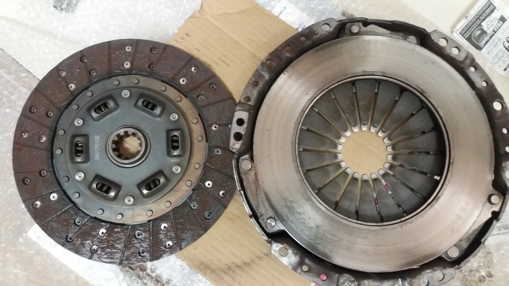
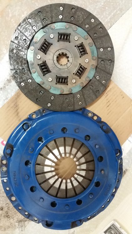
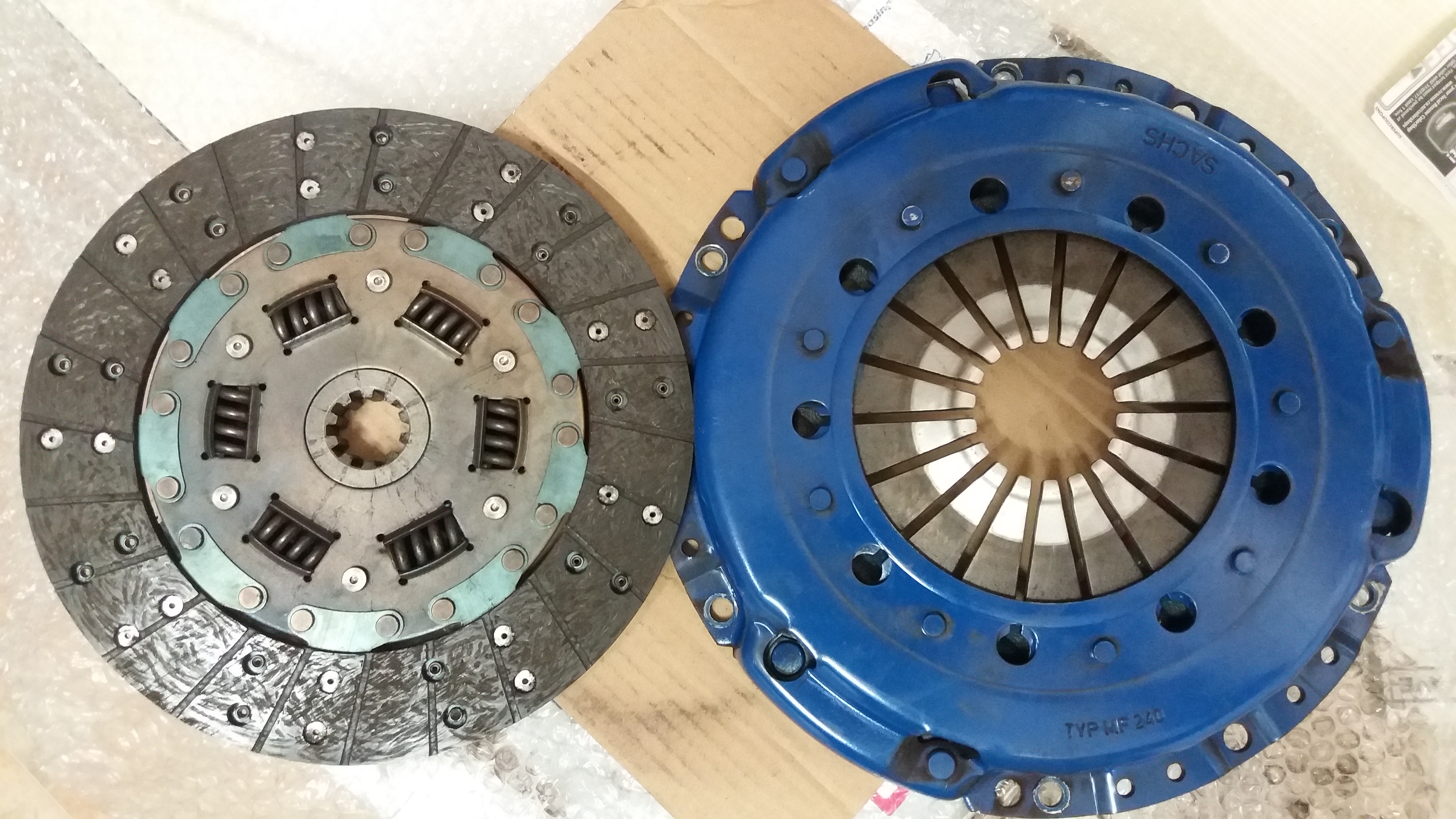
Sorry, this is a 240mm type for M50/S50/M52/S52 - original fitting was to an E36 M3 3.2 Evo + 6 Speed. The photo shows type MF 240..
I'm not sure what m20 / m30 fitment is...
-
I purchased this clutch as part of a NZAD D1 Racing Clutch kit which also came with a flywheel.
It was fitted between a M50B30 stroker engine (M54B30 crank) and a S6S-420G gearbox. It's done less than 3000km.
This combination did not work with clutch engagement only mm off the floor and crunchy gear changes very regularly due to improper disengagement. I put a standard S50 clutch plate and pressure plate in instead and haven't had any issues since. I'm still using the light flywheel that came in the D1 kit - it seems ok with the only issue being no TDC alignment hole!! I quite like what the light flywheel does for the way it revs. It does make the gearbox rattle like crazy when hot and at idle though.
Other members here have sucsessfully used this same kit with the 5 speed boxes but I'm selling this assuming it might not work.
The clutch worked ok, just incorrect engagement in my setup.
I'm looking for any offer of $50+ as I just want to move it on and not toss it in the bin. If you want it make me a silly offer - $50 will do + you pay the freight. I live in Napier so ask what the courier cost will be. I'm offering it to members here first and will put on TM if there's no interest.
-
Ah, bugger. It's the same box though isn't it, just a different bell housing (which is integrated into the front section of the box)?
-
Be really careful when modifying the original exhaust.
I made up a M50B30 stroker hybrid and the exhaust from a M3 Evo, headers right back to the rear muffler. The mid section wasn't in good shape so I dumped the cats and crossover section and initially went to straight pipes directly to the OEM rear muffler. The result was disastrous from a noise perspective. It was way too loud and very raspy. I ended up fitting an AdrenalineR 2-in/2-out muffler in the mid section where the ceossover used to be and went to 63mm tube from the headers to the new muffler. This made a big reduction in noise but killed the mid-range tourque and the rasp was still way to high. I'd effectively de-tuned the ehaust so it flowed poorly or even had a big negative impact in the mid-range rpm flow due to impropper back-wave timing. Next I changed the 63mm pipes to 50mm and fitted 2 new short resonators custom built by AdrenalieR in the same position as the original cats. This was to try to replicate the original exhaust and the resonator length was tuned to the mid-range rpm to create the proper timing for the back-wave and to effectively emulate the effect of the original cats. The result was mid-range torque again, no effect to the high rpm torque (perceived) and a lot less rasp.
When you muck around with non-standard exhaust combinations be prepared to spend a lot of extra time and money to rebuild it to get it right. Sometimes the apparent 'expensive' aftermarket options aren't actually that badly priced when you factor in it should work first time...
-
Wouldn't this fit?
http://www.trademe.co.nz/motors/car-parts-accessories/bmw/gear-boxes/auction-1242998507.htm
This is a 420G - I have one of these in my E36 but isn't it the same box as the 540?

Water Leak - E36 Coupe
in Maintenance
Posted · Report reply
Thanks, haven't checked this yet. I have a Link G4+ in this compartment and definately don't want water getting into it. I'll be checking this tonight for sure...
Some years ago I did get water in this compartment due to the drain in the heater area getting blocked and water would flow into the ECU compartment when going round a corner. It fried one of the coil driver smart transistors and I thought I'd need a new ECU. However, the local BMW shop showed me to a box of old blown ECU's so I robbed a transistor to replace into mine. Got it going again using the robbed part. I thought I'd solved the water problem by gluing in a baffle to stop water ever getting in there again. Worth checking it's still working + to see if water is somehow getting back in now...