topcat 11 Report post Posted January 30, 2010 just back from the welders. intercooler done,not conventional,but neither am i cage done, engine.....soon. i'm coming for ya Foxy Quote Share this post Link to post Share on other sites
Gotheschu 1 Report post Posted January 30, 2010 Post more pictures!!! Quote Share this post Link to post Share on other sites
Silver Fox 43 Report post Posted January 30, 2010 And I'm scared, not. Quote Share this post Link to post Share on other sites
3series 0 Report post Posted January 30, 2010 corporate cabs is expanding.. Quote Share this post Link to post Share on other sites
E30 325i Rag-Top 2915 Report post Posted January 30, 2010 intercooler done,not conventional,but neither am iLooks like an interesting project, I am keen to see it on the track in the flesh.From the addition of the intercooler I am pretty safe in saying you are going to run a turbo (or possibly supercharger), have you had the OK from the committee to run one, as I don't think they were standard on any model at the time? Quote Share this post Link to post Share on other sites
BM WORLD 1258 Report post Posted January 30, 2010 more pics Quote Share this post Link to post Share on other sites
BM WORLD 1258 Report post Posted January 30, 2010 Looks like an interesting project, I am keen to see it on the track in the flesh. From the addition of the intercooler I am pretty safe in saying you are going to run a turbo (or possibly supercharger), have you had the OK from the committee to run one, as I don't think they were standard on any model at the time? http://www.thealpinaregister.com/car.php?m...1§ion=2 http://www.thealpinaregister.com/cardetail...)§ion=2 http://aaron.aussiefiverdriver.com/E28%20history.htm http://bv911.free.fr/Ben/Alpina_B7_e28_198...303_Nov2006.PDF Quote Share this post Link to post Share on other sites
Creaver 55 Report post Posted January 31, 2010 (edited) Oh my......... Why do I think this is going to have a little more power than 315? Edited January 31, 2010 by Creaver - STOK3D Quote Share this post Link to post Share on other sites
OLLIE 26 Report post Posted January 31, 2010 Very Nice Marty! That intercooler is rather interesting, but i'm sure it'll do the trick. Keep us posted, can't wait to see how it goes Quote Share this post Link to post Share on other sites
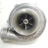
topcat 11 Report post Posted February 1, 2010 Looks like an interesting project, I am keen to see it on the track in the flesh. From the addition of the intercooler I am pretty safe in saying you are going to run a turbo (or possibly supercharger), have you had the OK from the committee to run one, as I don't think they were standard on any model at the time? no, your right. turbo's were not standard on these cars from factory. will be on the pleading matt before the committee at sum stage soon.but now that the 'rules' have been widened to include alpinas,hartge etc, it should be straight forward. altho, i could build a meaty oil burning diesel turbo version. e39/e34 535td into a an e28 could be the most interesting thing on the track not big HP's but 1000's of NM giggles, m Quote Share this post Link to post Share on other sites
topcat 11 Report post Posted February 22, 2010 Post more pictures!!! teaser 46mm tial t3 gt37 should work well.can make more,if your keen. moderator;can you put this in the project department,thanks Quote Share this post Link to post Share on other sites
E30BMA 0 Report post Posted February 23, 2010 Interesting manifold design...... is it just one big open chamber??? Surely that would effect the flow/spool time somewhat, compared to a tubular style manifold? Nice thread though, Ill be keeping a keen eye on this one. Quote Share this post Link to post Share on other sites
topcat 11 Report post Posted March 7, 2010 Interesting manifold design...... is it just one big open chamber??? Surely that would effect the flow/spool time somewhat, compared to a tubular style manifold? Nice thread though, Ill be keeping a keen eye on this one. probably alittle restrictive,but research i've come across regarding a tubular manifold is that great gains are to be made if running over 500hp setups. people often forget that there's pressure inside the log.how much pressure is dependent on the wastegate spring.eg; running 15psi boost=15psi of pressure in the exhaust manifold. the exhaust pulses should work on spool up regardless of shape. m Quote Share this post Link to post Share on other sites
topcat 11 Report post Posted March 7, 2010 more teasin' Quote Share this post Link to post Share on other sites
Eddie 66 Report post Posted March 7, 2010 probably alittle restrictive,but research i've come across regarding a tubular manifold is that great gains are to be made if running over 500hp setups. people often forget that there's pressure inside the log.how much pressure is dependent on the wastegate spring.eg; running 15psi boost=15psi of pressure in the exhaust manifold. the exhaust pulses should work on spool up regardless of shape. m I was told by a valve spring supplier to allow 3X boost pressure = back pressure on the exhaust valve. ie. 20psi boost = 60 psi exhaust pressure Anyone else heard of this, or was I just told a pile of poo Quote Share this post Link to post Share on other sites
antil33t 90 Report post Posted March 7, 2010 Looks good man! Quote Share this post Link to post Share on other sites
CamB 48 Report post Posted March 7, 2010 I was told by a valve spring supplier to allow 3X boost pressure = back pressure on the exhaust valve. ie. 20psi boost = 60 psi exhaust pressure Anyone else heard of this, or was I just told a pile of poo I've found the following (and found it very helpful) on backpressure. (Martyn - let me know if you don't want your thread scuzzed up by this semi-off topic stuff). The first is from a guy called Jay Kavanagh who was a Garrett engineer and wrote for a variety of US magazines in a tech capacity: FWIW I'm an turbocharger development engineer for Garrett Engine Boosting Systems. N/A cars: As most of you know, the design of turbo exhaust systems runs counter to exhaust design for n/a vehicles. N/A cars utilize exhaust velocity (not backpressure) in the collector to aid in scavenging other cylinders during the blowdown process. It just so happens that to get the appropriate velocity, you have to squeeze down the diameter of the discharge of the collector (aka the exhaust), which also induces backpressure. The backpressure is an undesirable byproduct of the desire to have a certain degree of exhaust velocity. Go too big, and you lose velocity and its associated beneficial scavenging effect. Too small and the backpressure skyrockets, more than offsetting any gain made by scavenging. There is a happy medium here. For turbo cars, you throw all that out the window. You want the exhaust velocity to be high upstream of the turbine (i.e. in the header). You'll notice that primaries of turbo headers are smaller diameter than those of an n/a car of two-thirds the horsepower. The idea is to get the exhaust velocity up quickly, to get the turbo spooling as early as possible. Here, getting the boost up early is a much more effective way to torque than playing with tuned primary lengths and scavenging. The scavenging effects are small compared to what you'd get if you just got boost sooner instead. You have a turbo; you want boost. Just don't go so small on the header's primary diameter that you choke off the high end. Downstream of the turbine (aka the turboback exhaust), you want the least backpressure possible. No ifs, ands, or buts. Stick a Hoover on the tailpipe if you can. The general rule of "larger is better" (to the point of diminishing returns) of turboback exhausts is valid. Here, the idea is to minimize the pressure downstream of the turbine in order to make the most effective use of the pressure that is being generated upstream of the turbine. Remember, a turbine operates via a pressure ratio. For a given turbine inlet pressure, you will get the highest pressure ratio across the turbine when you have the lowest possible discharge pressure. This means the turbine is able to do the most amount of work possible (i.e. drive the compressor and make boost) with the available inlet pressure. Again, less pressure downstream of the turbine is goodness. This approach minimizes the time-to-boost (maximizes boost response) and will improve engine VE throughout the rev range. As for 2.5" vs. 3.0", the "best" turboback exhaust depends on the amount of flow, or horsepower. At 250 hp, 2.5" is fine. Going to 3" at this power level won't get you much, if anything, other than a louder exhaust note. 300 hp and you're definitely suboptimal with 2.5". For 400-450 hp, even 3" is on the small side.” "As for the geometry of the exhaust at the turbine discharge, the most optimal configuration would be a gradual increase in diameter from the turbine's exducer to the desired exhaust diameter-- via a straight conical diffuser of 7-12° included angle (to minimize flow separation and skin friction losses) mounted right at the turbine discharge. Many turbochargers found in diesels have this diffuser section cast right into the turbine housing. A hyperbolic increase in diameter (like a trumpet snorkus) is theoretically ideal but I've never seen one in use (and doubt it would be measurably superior to a straight diffuser). The wastegate flow would be via a completely divorced (separated from the main turbine discharge flow) dumptube. Due the realities of packaging, cost, and emissions compliance this config is rarely possible on street cars. You will, however, see this type of layout on dedicated race vehicles. A large "bellmouth" config which combines the turbine discharge and wastegate flow (without a divider between the two) is certainly better than the compromised stock routing, but not as effective as the above. If an integrated exhaust (non-divorced wastegate flow) is required, keep the wastegate flow separate from the main turbine discharge flow for ~12-18" before reintroducing it. This will minimize the impact on turbine efficiency-- the introduction of the wastegate flow disrupts the flow field of the main turbine discharge flow. Necking the exhaust down to a suboptimal diameter is never a good idea, but if it is necessary, doing it further downstream is better than doing it close to the turbine discharge since it will minimize the exhaust's contribution to backpressure. Better yet: don't neck down the exhaust at all. Also, the temperature of the exhaust coming out of a cat is higher than the inlet temperature, due to the exothermic oxidation of unburned hydrocarbons in the cat. So the total heat loss (and density increase) of the gases as it travels down the exhaust is not as prominent as it seems. Another thing to keep in mind is that cylinder scavenging takes place where the flows from separate cylinders merge (i.e. in the collector). There is no such thing as cylinder scavenging downstream of the turbine, and hence, no reason to desire high exhaust velocity here. You will only introduce unwanted backpressure. Other things you can do (in addition to choosing an appropriate diameter) to minimize exhaust backpressure in a turboback exhaust are: avoid crush-bent tubes (use mandrel bends); avoid tight-radius turns (keep it as straight as possible); avoid step changes in diameter; avoid "cheated" radii (cuts that are non-perpendicular); use a high flow cat; use a straight-thru perforated core muffler... etc.” "Comparing the two bellmouth designs, I've never seen either one so I can only speculate. But based on your description, and assuming neither of them have a divider wall/tongue between the turbine discharge and wg dump, I'd venture that you'd be hard pressed to measure a difference between the two. The more gradual taper intuitively appears more desirable, but it's likely that it's beyond the point of diminishing returns. Either one sounds like it will improve the wastegate's discharge coefficient over the stock config, which will constitute the single biggest difference. This will allow more control over boost creep. Neither is as optimal as the divorced wastegate flow arrangement, however. There's more to it, though-- if a larger bellmouth is excessively large right at the turbine discharge (a large step diameter increase), there will be an unrecoverable dump loss that will contribute to backpressure. This is why a gradual increase in diameter, like the conical diffuser mentioned earlier, is desirable at the turbine discharge. As for primary lengths on turbo headers, it is advantageous to use equal-length primaries to time the arrival of the pulses at the turbine equally and to keep cylinder reversion balanced across all cylinders. This will improve boost response and the engine's VE. Equal- length is often difficult to achieve due to tight packaging, fabrication difficulty, and the desire to have runners of the shortest possible length.” "Here's a worked example (simplified) of how larger exhausts help turbo cars: Say you have a turbo operating at a turbine pressure ratio (aka expansion ratio) of 1.8:1. You have a small turboback exhaust that contributes, say, 10 psig backpressure at the turbine discharge at redline. The total backpressure seen by the engine (upstream of the turbine) in this case is: (14.5 +10)*1.8 = 44.1 psia = 29.6 psig total backpressure So here, the turbine contributed 19.6 psig of backpressure to the total. Now you slap on a proper low-backpressure, big turboback exhaust. Same turbo, same boost, etc. You measure 3 psig backpressure at the turbine discharge. In this case the engine sees just 17 psig total backpressure! And the turbine's contribution to the total backpressure is reduced to 14 psig (note: this is 5.6 psig lower than its contribution in the "small turboback" case). So in the end, the engine saw a reduction in backpressure of 12.6 psig when you swapped turbobacks in this example. This reduction in backpressure is where all the engine's VE gains come from. This is why larger exhausts make such big gains on nearly all stock turbo cars-- the turbine compounds the downstream backpressure via its expansion ratio. This is also why bigger turbos make more power at a given boost level-- they improve engine VE by operating at lower turbine expansion ratios for a given boost level. As you can see, the backpressure penalty of running a too-small exhaust (like 2.5" for 350 hp) will vary depending on the match. At a given power level, a smaller turbo will generally be operating at a higher turbine pressure ratio and so will actually make the engine more sensitive to the backpressure downstream of the turbine than a larger turbine/turbo would. As for output temperatures, I'm not sure I understand the question. Are you referring to compressor outlet temperatures? The second is from (it seems) a dude at "Forced Performance": Here is a big one, I am going to let a big secret (for some) out of the bag here for you guys so bear with me through this. First of all, know that there are compressor housing A/R’s and turbine housing A/R’s. Since turbine housing A/R is likely the context of your question I will address that here. A/R ratio is a term we use in the industry to differentiate flow capacities between like housings with similar exterior dimensions with different size volutes. What is a volute? A volute is the spiral shaped cone on the inside diameter of the turbine housing that begins right about the point in the housing where you can no longer see into it, after the inside diameter changes from the shape of the flange opening to the shape of the volute (usually a teardrop shape). The volutes job is to harness the energy (heat, pressure, velocity and sound) from your motor and concentrate it onto the turbine wheel to generate power to turn the compressor wheel. The number designation given is a ratio derived by taking the cross-section area of the beginning of the volute over the distance from the middle of the cross-section to the center of the turbine wheel (axis). So what does this number tell you about flow? By itself, …nothing. This number is used to compare housings of similar castings with the only difference being the volute. Here is where I am going with this. Say you have a housing whose area is 1.45 in2 over a radius of 1.69 inches, that makes the A/R= .85. Well, say you have another housing whose area is 1.8 in2 over a 2.1 inches radius. Well, the A/R is still .85 so that means they flow the same …right? WRONG! So what does that tell us? You cannot compare turbine housings between families just by the A/R. Reason I go into this is that I have people ask me all the time what the A/R of a FP30 housing is. Why? There is only one FP30 volute, so how is knowing what it’s A/R is relevant? You can however compare the A/R between all T31 housings, or all T4 housing, etc. The shape of the volute can affect the way the potential energy is harnessed. The closer to the shape of a teardrop the volute takes, the easier energy is transferred around the housing and into the turbine wheel. Most OEM castings like the 7cm Mitsu housings have a compromised volute (teardrop cut in half) for water line clearance to the bearing housing and ease of casting. On the other hand, most aftermarket housings like the FP30 and Garrett T31 housings have a better shaped volute patterned after Garrett Motorsports housings for maximum efficiency. Here is where A/R comes in to play. Say you are buying a straight Garrett 50 trim with a Stage III turbine wheel. When it comes to the turbine housing you have 3 popular choices. You have a .49, .63, and .82. They all have very similar exterior dimensions and look exactly alike but on the inside they are very different. NOTE: The following scenarios include hypothetical spool times and performance numbers used to illustrate the difference between turbine housing sizes and may not necessarily reflect the performance characteristics of this specific combination on your car exactly. The .49 has the smallest volute so it will make our turbo respond fast, with the least amount of lag of the 3 choices. This small volute makes it spool fast but once the turbo is spooled and the wastegate is open, this small volute now becomes a restriction to the flow of exhaust gas speeding out of the manifold looking for freedom to the atmosphere. Backpressure (pressure that builds in the manifold before the turbos turbine) builds to 63psi before the turbine and less and less exhausted air/fuel mixture is allowed to exit the combustion chamber which limits your horsepower. You reach 20psi of boost by 3400rpm but because of your diluted A/F mixture in the cylinders you reach 345 hp by 5700rpm at 20psi. This makes a great autocross turbo because you make plenty of power down low with enough torque at the bottom of third gear in turn 4 to pick up half a second lap time. Say you decide to go with the .63 turbine housing. Instead of 63psi of backpressure you only get 33psi. This allows a cleaner charge in the combustion chamber. A lot less backpressure builds in the manifold and as a result you make much more power on top, as much as 360hp by 5700rpm. The penalty is that instead of reaching 20psi of boost by 3400rpm, you don’t see 20psi till 3700. This can be a much better compromise for a car driven on the street that sees occasional duty at the local drag strip. All out setups that demand every ounce of performance from their turbocharger require the largest A/R they can tolerate within reason. The .82 housing offers the least restriction to flow of the three. You may not see 20psi till 4000, but you’ll be able to hit 380hp on pump at that boost. Backpressure is kept in the high 20’s. Restriction varies with mod level. Guys with fewer mods that affect VE are less affected by the restriction a smaller housing. So, for a guy with a stock motor with basic upgrades a .49 housing might be nice. By the time you add heavy cams, port the head, install a sheet metal intake many, etc. even a .63 A/R housing might be out of the question. Conversely, a guy with a stock motor might not see any better backpressure readings with a .82 than with a .63, now all he has is a lazy car. For help on where you should start, share your data with friends that have similar setup’s that have backpressure data, or get the advice of an experienced turbo professional. Most people never know what their back pressure is. I mean how many of us really have a pressure transducer tapped in their manifold? I’ll tell you, I see it without fail. All these guys have that ridiculous EGT gauge tapped religiously in their #1 runner. I honestly think only the Autometer blinky light A/F meter for a narrow band OEM O2 sensor a more worthless piece of sh*t gauge to occupy gauge space, but I digress. You don’t have to have a gauge permanently mounted in sight for backpressure. Only need to make this measurement after you make a change that affects your engine VE. VE is volumetric efficiency. VE is a measure of your engines ability to move air through it. Head porting, camshafts, intake manifolds, air filters, intercoolers, turbos and exhaust systems all affect your engines VE. Examples of modifications that don’t affect your VE are fuel injectors, piggyback ECU controllers, blow-off valves, fuel pressure regulators, fuel pumps, and MSD ignitions. You also don’t have to have a fancy stand-alone ECU with an expensive 5 bar MAP to take backpressure measurements. Next time you are in AutoZone, take a look in the hillbilly section. Next to the chrome naked girl silhouette mud flaps you’ll find cheap oil pressure gauges. Pull that stupid EGT probe out temporarily and run some copper tubing to the hole with a 1/8 NPT compression fitting. Run enough tubing to protect the gauge from the heat of the exhaust manifold. Then run rubber tubing to a generic fuel filter assembly, then run more tubing to the cockpit to that bitchin oil pressure gauge. The fuel filter acts as a dampener to reduce the pressure oscillations from the exhaust “putts” and allow you to make a cleaner measurement. Get a friend to ride with you to watch the gauge. The gauge may not even flinch till you hit boost, but then should rise quickly with boost and continue climbing with RPM till you reach your engines max VE point then taper off (usually around 5700 with a stock intake manifold). So now that you have your backpressure reading how much is too much? Generally speaking, you don’t want more than a 1:1.5 ratio of boost to backpressure. So if you’re at 20psi of boost you should not see more than 30-35psi of backpressure. If you do then you should upgrade the turbine side, you’ll make more horsepower for every pound of boost you run. Turbine wheels and exhaust system diameters can also affect your backpressure reading, but to stay on topic I will address turbine wheels and pipes later on. For the most part, turbine wheels being part of the CHRA, are not easily changed by the average do-it-yourself tuner. For now, just know that if you upgrade your housing and your backpressure reading doesn’t come down where it should, your problem might be your turbine wheel. If this is the case or if larger turbine housings are not available you might consider a complete turbo change. Stay tuned… Quote Share this post Link to post Share on other sites
E30 325i Rag-Top 2915 Report post Posted March 7, 2010 (edited) Reckon you'll be ready for the last round at Hampton ? Good to see it coming along, looks like you're getting down to the nitty gritty stuff now, fingers crossed it all goes to plan! Edited March 7, 2010 by E30 325i Rag-Top Quote Share this post Link to post Share on other sites
topcat 11 Report post Posted March 8, 2010 cheers for the post-up of the article Cam. no hyjacking mate,usefull info. yes,equal length runners are the best option,in any set-up. but e28 chassis rails have other things to say about that. engine bay is tight,compared to a e34,even a e24 has more room. this is why a log is the easiest way around the problem,and its a sh*t load cheaper. would like to be there for hampton,but i'm losing a a few pints of motovation athe moment. the $$$ are strating to mount up,and i havnt even looked at the suspension yet m Quote Share this post Link to post Share on other sites
topcat 11 Report post Posted March 27, 2010 bit more got done,looks more like what is suppose to be. needs a three inch drop,next saving plan Quote Share this post Link to post Share on other sites
topcat 11 Report post Posted April 19, 2010 (edited) now to start inside. tidy and out of the way,while still being able to service it all,if required.(hopefully not) not much left to do now.yay who-ever invented cable ties deserves a medal Edited April 19, 2010 by BM Weapon Quote Share this post Link to post Share on other sites
melowpuf 19 Report post Posted April 19, 2010 (edited) I'm sorry Marty.. I owe you 2 car washes now.. I'll bring my bikini on saturday.. Show the punters the secret cooling weapons I'm looking forward to this next coming month.. should be lots of excitement.. maybe a christening/naming ceremony and then show everyone what a real car is.. Oh and Brent was saying the Non aircon versions had a compartment in the console which could possibly be used as an access to get to your fuses and relays easily instead of pulling the console out.. any lying around to have a look? Edited April 19, 2010 by melowpuf Quote Share this post Link to post Share on other sites
topcat 11 Report post Posted May 26, 2010 (edited) well its been awhile now,and afew more things have been tampered with. its amazing the hours go into this sort of thing. 5 out of 7 nights in the week,spending at least 3hrs, and weekends. i have a new respect for all of you who have and are working on race/ground-up rebuilds etc. saying that,i have done a couple of engines etc,but this project has taken the cake. as of this afternoon,this is where were at. ITS ROLLING UNDER ITS OWN POWER,alittle celebration as the wife was wondering if this thing was ever coming off the hoist without me pushing.(for a while I was wondering the same thing) its come a long way, but not far now till its tarmac ready. the suspension has been changed over for coil-overs,care of stocks,cheers Grant/Russell. Wheels are 18's.think they look OK,not sure.alittle modern but they will have to do for now. cheers Dave(foxy) for lending me the spacer's to clear the wheel.2mm was all it needs the upgraded brakes work an absolute treat.really looking forward to trying 'em out on the track. the money shot. sooo glad the way the engine bay looks.engine is running very well,and no exhaust leaks. had my fingers crossed this morning as it was the first time the system was pressurized. the down and wastegate pipe was the biggest job.didnt take pics of those bits on the table, but they took forever to 'get right' as its tight between the exhaust mani and steering box. thought i'd try something different to most(again).3 inch straight thru and the waste has its own plumbing.the two merge just before the nasty gangster upswung square chrome tip trademe special muffler qiute a mouth full,but best describes the specialness of it bit of shame I couldnt finnish it off this week as today the cert man came round to check out my machine.altho id spend all weekend and the last two nights till 2am. the list of 'to do' for the cert requirements is short.and are really minor things like door trims/coverings,seal firewall,rollcage foam,fit the bumpers and mount the passenger seat so nothing major.yay for me. Many thanks to God(giving me a good imagination)Lance(mellowpuff),Denise,Brent,Jason(macweld,for the awesome catch tank and other welding) the guys from Drury Auto Service(Garry and Markus),Oliver(frantik motorsports) Ciska(iced performance,fibreglassing and body kits) and a patient wife and i wasnt to call him untill i had fixed/deleted the smoke screen option. i told him its for the race track only,but he didnt want a bar of it happy days Edited May 27, 2010 by BM Weapon Quote Share this post Link to post Share on other sites
melowpuf 19 Report post Posted May 26, 2010 HAHAHA DORK! Honestly I don't know how you got that much done in the last 3 days. We literally pulled a turbo out of a 180sx on Sunday night to donate, so you could plumb up your exhaust and wastegate to get you through the certing today because yours is on a boat in the amazon somewhere, only to find it was of no use to you. Last night you arrive home at 8?? with a "reconditioned" turbo from your turbo guy to tie you over until the real one arrives, comments of praise from the Cert guy for the intricate fabrication that had been put into the exhaust system. Cert man will be back next week Marty ... YOU CAN DO IT!!!!!!!!!!!! and where are the other pics?? there are much better ones Quote Share this post Link to post Share on other sites
zenetti 0 Report post Posted May 27, 2010 I can't see the silver belts Quote Share this post Link to post Share on other sites