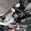
central3 31 Report post Posted March 4, 2014 (edited) I have been in 2 minds as to whether I should post my experience with the dreaded E46 M3 chassis crack, on one hand it is negative for resale purposes while on the other it is potentially good information for fellow Bimmersporters and I reckon the repair is up to any scrutiny. I found the crack after viewing a Reddish Motorsport video, I had looked before (with the entire subframe out) but I did not look in all of the right places so I don’t know if is new or was existing. In my case the crack was located in the classic spot (i.e. left hand rear subframe mount at the floor crease). Why do our cars fail here? Don’t know but previously we could comfort ourselves that very few cars were affected but it seems to me that as time goes on (i.e. km’s) the instances increase exponentially. After stripping the vehicle underside and inspecting all of the subframe mounting points I found that there was only 1 crack and that it was fairly small (30mm long). Based on this I decided to weld the crack, fit reinforcing plates, inject BMW structural “foam” and repaint the underneath of the car. Bearing in mind that the size of the crack (small) + the internal and external reinforcing being applied I chose to epoxy the reinforcement plates on rather than weld them. I had the necessary gear/skills to weld and it would have been cheaper but I felt it would have been too “invasive” when all things were taken into account. I also decided to use the structural foam in the LHR and RHF cavities as these are the 2 places where the cracking normally begins. This is because the LHR subframe mount is subjected to tensile stress (from motor induced rotational torque (anti-clockwise look at the rear of the car) and axle induced rotational torque (anti-clockwise looking at the right hand rear wheel). The RHF subframe mount is subjected to compression stress (i.e. the opposite of the LHR). The other 2 mounts (and ultimately the whole floor panel) really only seem to fail once these 2 stressed mounts have failed. There are plenty of DIY’s out there so I haven’t gone into the full detail here, a few things to note though. Regarding the rear mount, since I had the subframe out I chose to blank off the rear cavity (using expanding foam) from the bottom of the car rather than inside the boot as per BMW’s T.I.S. Regarding the front mount, I spent a lot of time estimating the size of the cavity that the mounts are encased in and found that it is quite large. This prompted me to use expanding foam to keep the structural epoxy localised around the mounting point, this is not something I have seen done before. A lot of people use a hand actuated epoxy applicator gun but this is very hard work, instead I made up a mechanised unit as per the following photos. Regarding costs the BMW structural foam was $263 per pack (2 x 420ml tube pairs) – I brought 2 packs. The reinforcement plate epoxy was $40/tube – I brought 4 but could have got away with 2. If anyone is interested I have the gear I used for this job available (diff/axle carrier frame, reinforcement plate templates, reinforcement plate clamps and foam dispenser gun). 1. Crack viewed through the RHR sway bar mount (exhaust removed) 2. Close up of the crack 3. Home-made reinforcement plates (2.0mm) 4. Underside stripped and mounting points cleaned up 5. LHR mount ok apart from crack to the left (you need to look out for separated spot welds as well as cracks) 6. LHF ok 7. RHF ok (circular shape around thread is not a crack, it is the boundary line between the body panel and the threaded insert) 8. RHR ok 9. Crack ends drilled 10. Crack welded (gas - 2 passes) 11. Plates coated with epoxy after scouring with 60 grit and cleaning with electrical contact cleaner 12. Reinforcing plates fitted and compressed into place with 2D clamping plates (rear), not something I have seen done but a must I reckon 13. Front reinforcing and clamping plates (all left in position for 1 week) 14. Car fully masked in preparation for underside painting 15. Underside primed after degrease, scuffing and prepsol cleaning 16. LHR mount after base and clear coat 17. RHR mount after colour 18. LHF mount after colour 19. RHF mount after colour 20. Fuel tank back in 21. Rear axle on its way back in (note blue painted support tool which made the process quick and easy) 22. Expanding foam being applied between rear mounts as per the T.I.S 23. Expanding foam being applied to RHS of front mount cavity (through OEM drilling) – LH done too (although I didn’t fill the LHS with structural foam I prepared all sides in case I want to do at a future date) 24. Expanding foam being applied to the centre of front mount cavity (through new drilling) 25. Expanding foam being applied to the “tunnel” that runs between the front and rear cavities (modified version of T.I.S method) 26. Holes plugged (plugs at 11:00 and 4:00 o’clock in photo) 27. 4 x BMW structural foam packs plus homemade applicator gun 28. Applicator being used to fill RHF subframe mount cavity 29. Applicator being used to fill LHR subframe mount cavity Last photos show exhaust re-polished and rear box – 3rd and final piece of work in the “gutting” exercise - last remaining fibreglass packing removed from the inlet section (patch at 2:00 the only evidence) plus underfloor plastics repainted Edited March 4, 2014 by central3 3 Quote Share this post Link to post Share on other sites
yng_750 247 Report post Posted March 4, 2014 Absolutly top notch work Sent from my GT-I8160L using Tapatalk 2 Quote Share this post Link to post Share on other sites
Eagle 1776 Report post Posted March 4, 2014 ^+1 Quote Share this post Link to post Share on other sites
gjm 3300 Report post Posted March 4, 2014 Paul - thank you for sharing. I understand your concerns, but as is the case with the vast majority of repairs - if carried out properly it is not going to affect the vehicle in any way. And it provides invaluable insight for other owners. Quote Share this post Link to post Share on other sites
FIAT 131R 223 Report post Posted March 4, 2014 That's some very professional work. Quote Share this post Link to post Share on other sites
Michael. 2313 Report post Posted March 4, 2014 I'm doing this to my E36 as we speak! But god lord, that is so clean, quite unbelievably so! Quote Share this post Link to post Share on other sites
BreakMyWindow 1965 Report post Posted March 4, 2014 Amazing attention to detail, and some really cool diy tools made there to help you with this. Love ya work. Quote Share this post Link to post Share on other sites
Elvis 3 Report post Posted March 4, 2014 Brilliant - thank you for sharing If its a manual I would buy in heartbeat. So many repairs are done as bog + flogs Well documented issue & unlikely to be uninformed buyers out there Quote Share this post Link to post Share on other sites
M3_Power 636 Report post Posted March 4, 2014 (edited) Amazing work as per usual Paul. You should also note that you are a ticketed welder so this is NOT a backyard type repair. I don't think anyone would hesitate to buy this car with all the attention to detail you pay to each and every time you work on this car. p.s. Where did you get the rear axle carrier from? Is it a brand specific unit or a generic one that you purchased?? p.s.s Love the home made epoxy applicator gun/drill!!! (you should hire it out to BMW or better still, mass produce it and sell it on m3forums : P) I do have one question however - how come you didn't make the LHR reinforcement plate larger so that it boxed in the repaired crack? Edited March 4, 2014 by M3_Power Quote Share this post Link to post Share on other sites
Tristan 338 Report post Posted March 4, 2014 Admirable to say the least! 1 Quote Share this post Link to post Share on other sites
hybrid 1045 Report post Posted March 4, 2014 I agree, would much rather buy a car thats had it dealt with than not. Top notch work as usual Quote Share this post Link to post Share on other sites
central3 31 Report post Posted March 4, 2014 I'm doing this to my E36 as we speak! But god lord, that is so clean, quite unbelievably so! Yes I have been watching you with interest - I would love to have a go at a rear mount brace as per your design, cool project - bit too much for mine though as I want to keep it pretty close to stock - absolutely appropriate for your machine though Amazing work as per usual Paul. You should also note that you are a ticketed welder so this is NOT a backyard type repair. I don't think anyone would hesitate to buy this car with all the attention to detail you pay to each and every time you work on this car. p.s. Where did you get the rear axle carrier from? Is it a brand specific unit or a generic one that you purchased?? p.s.s Love the home made epoxy applicator gun/drill!!! (you should hire it out to BMW or better still, mass produce it and sell it on m3forums : P) I do have one question however - how come you didn't make the LHR reinforcement plate larger so that it boxed in the repaired crack? Cheers Tom and thanks for your advise leading up to this work - the diff carrier is homemade but semi-modelled off that which Reddish Motorsport use - don't think I will be hiring or manufacturing tools (fully available to bona fide BS members though). I did not plate over the crack repair as a good weld with reinforcement (i.e. the weld cap) is I think better than a ground down weld with plating (especially when working with sheetmetal I think). Also because the crack is at a shape transition point it would be hard to get a perfect/tight fit - for best strength the epoxy joint needs to be thin. When do we do the CSL? Quote Share this post Link to post Share on other sites
M3_Power 636 Report post Posted March 5, 2014 Cheers Tom and thanks for your advise leading up to this work - the diff carrier is homemade but semi-modelled off that which Reddish Motorsport use - don't think I will be hiring or manufacturing tools (fully available to bona fide BS members though). I did not plate over the crack repair as a good weld with reinforcement (i.e. the weld cap) is I think better than a ground down weld with plating (especially when working with sheetmetal I think). Also because the crack is at a shape transition point it would be hard to get a perfect/tight fit - for best strength the epoxy joint needs to be thin. When do we do the CSL? No problem Paul, more than happy to help with my opinions haha!!! Looks like you've adopted quite a good solution to it all. Nice work with the home made diff carrier!! It's times like this that I wished I could weld!! LOL Appreciate the explanation on not plating over the weld, I figured that may have been the case but wasn't quite sure looking at the photos if you had grinded down the weld. As for the CSL ... As I've said before, the day I find a crack on it is the day it gets turned into a racecar Quote Share this post Link to post Share on other sites
central3 31 Report post Posted March 15, 2014 After recieving the last parts required (graphite exhaust gaskets ex germany) I finally have her back on the road. Last shots of the refurbished underside. I am at last happy with the exhaust. Ist step last year was to replace the pipes in compartment 3 with straight through jobies - made very little difference. 2nd step was to remove the fiberglass packing in compartment 2 - slightly more noise under load but not much in it. Final step was to remove th fibreglass packing in section 1 - quite different now. Deeper note at idle and quite raucous after 3,000 rpm. No drone at highway speed and looks nice and stock. Quote Share this post Link to post Share on other sites
Lewis91 114 Report post Posted March 15, 2014 Epic work. Quote Share this post Link to post Share on other sites
Dkr 0 Report post Posted May 7, 2014 I have been in 2 minds as to whether I should post my experience with the dreaded E46 M3 chassis crack, on one hand it is negative for resale purposes while on the other it is potentially good information for fellow Bimmersporters and I reckon the repair is up to any scrutiny. I found the crack after viewing a Reddish Motorsport video, I had looked before (with the entire subframe out) but I did not look in all of the right places so I don’t know if is new or was existing. In my case the crack was located in the classic spot (i.e. left hand rear subframe mount at the floor crease). Why do our cars fail here? Don’t know but previously we could comfort ourselves that very few cars were affected but it seems to me that as time goes on (i.e. km’s) the instances increase exponentially. After stripping the vehicle underside and inspecting all of the subframe mounting points I found that there was only 1 crack and that it was fairly small (30mm long). Based on this I decided to weld the crack, fit reinforcing plates, inject BMW structural “foam” and repaint the underneath of the car. Bearing in mind that the size of the crack (small) + the internal and external reinforcing being applied I chose to epoxy the reinforcement plates on rather than weld them. I had the necessary gear/skills to weld and it would have been cheaper but I felt it would have been too “invasive” when all things were taken into account. I also decided to use the structural foam in the LHR and RHF cavities as these are the 2 places where the cracking normally begins. This is because the LHR subframe mount is subjected to tensile stress (from motor induced rotational torque (anti-clockwise look at the rear of the car) and axle induced rotational torque (anti-clockwise looking at the right hand rear wheel). The RHF subframe mount is subjected to compression stress (i.e. the opposite of the LHR). The other 2 mounts (and ultimately the whole floor panel) really only seem to fail once these 2 stressed mounts have failed. There are plenty of DIY’s out there so I haven’t gone into the full detail here, a few things to note though. Regarding the rear mount, since I had the subframe out I chose to blank off the rear cavity (using expanding foam) from the bottom of the car rather than inside the boot as per BMW’s T.I.S. Regarding the front mount, I spent a lot of time estimating the size of the cavity that the mounts are encased in and found that it is quite large. This prompted me to use expanding foam to keep the structural epoxy localised around the mounting point, this is not something I have seen done before. A lot of people use a hand actuated epoxy applicator gun but this is very hard work, instead I made up a mechanised unit as per the following photos. Regarding costs the BMW structural foam was $263 per pack (2 x 420ml tube pairs) – I brought 2 packs. The reinforcement plate epoxy was $40/tube – I brought 4 but could have got away with 2. If anyone is interested I have the gear I used for this job available (diff/axle carrier frame, reinforcement plate templates, reinforcement plate clamps and foam dispenser gun). 1. Crack viewed through the RHR sway bar mount (exhaust removed) 1.jpg 2. Close up of the crack 2.jpg 3. Home-made reinforcement plates (2.0mm) 3.jpg 4. Underside stripped and mounting points cleaned up 4.jpg 5. LHR mount ok apart from crack to the left (you need to look out for separated spot welds as well as cracks) 5.jpg 6. LHF ok 6.jpg 7. RHF ok (circular shape around thread is not a crack, it is the boundary line between the body panel and the threaded insert) 7.jpg 8. RHR ok 8.jpg 9. Crack ends drilled 9.jpg 10. Crack welded (gas - 2 passes) 10.jpg 11. Plates coated with epoxy after scouring with 60 grit and cleaning with electrical contact cleaner 11.jpg 12. Reinforcing plates fitted and compressed into place with 2D clamping plates (rear), not something I have seen done but a must I reckon 12.jpg 13. Front reinforcing and clamping plates (all left in position for 1 week) 13.jpg 14. Car fully masked in preparation for underside painting 14.jpg 15. Underside primed after degrease, scuffing and prepsol cleaning 15.jpg 16. LHR mount after base and clear coat 16.jpg 17. RHR mount after colour 17.jpg 18. LHF mount after colour 18.jpg 19. RHF mount after colour 19.jpg 20. Fuel tank back in 20.jpg 21. Rear axle on its way back in (note blue painted support tool which made the process quick and easy) 21.jpg 22. Expanding foam being applied between rear mounts as per the T.I.S 22.jpg 23. Expanding foam being applied to RHS of front mount cavity (through OEM drilling) – LH done too (although I didn’t fill the LHS with structural foam I prepared all sides in case I want to do at a future date) 23.jpg 24. Expanding foam being applied to the centre of front mount cavity (through new drilling) 24.jpg 25. Expanding foam being applied to the “tunnel” that runs between the front and rear cavities (modified version of T.I.S method) 25.jpg 26. Holes plugged (plugs at 11:00 and 4:00 o’clock in photo) 26.jpg 27. 4 x BMW structural foam packs plus homemade applicator gun 27.jpg 28. Applicator being used to fill RHF subframe mount cavity 28.jpg 29. Applicator being used to fill LHR subframe mount cavity 29.jpg Last photos show exhaust re-polished and rear box – 3rd and final piece of work in the “gutting” exercise - last remaining fibreglass packing removed from the inlet section (patch at 2:00 the only evidence) plus underfloor plastics repainted Sensational Quote Share this post Link to post Share on other sites
Dkr 0 Report post Posted July 2, 2014 Hi Paul, well I have just completed the chassis repair on my e46m3, with your post and countless hours spent googling options I finally got into it and the whole project went extremely well. Standard procedure was followed to strip and prep area for repair, I did opt to fully weld stiffening plates to all 4 areas in question, the initial crack was about 40 mm long on front RH mount, this being typical failure point but my car also had slight deformation of the folded sheet metal tub that the sub frame actually bolts to, it does show just how much torsional up load this area is subjected to. So with the areas prepped, new plates made I fully welded these in place taking care not to over heat the entire area. The repair was pretty straight forward and the result was very Profesional, zinc based chassis repair paint was used to seal and protect the exposed bare metal (two coats) then full under body seal was applied, with car all back together you would have to be an expert on this type of repair to spot it. Rear muffler was also cut open removing the packing material as you did, ummmm not a lot of difference to be honest...almost not worth the effort however looking at removing the cats now. Another mod was to machine up some poly board plastic spacers to stop side trust on front bushes ( these I also replaced along with all bushes ossiciated with the sub frame) these mounts are bolted up just In front of the rear wheel arch, huge improvement under heavy load gear changes, stops that little side ways kick and keeps car in straight line. Last thing was to apply the BMW structural foam as per TIS recommendations along with the extra areas that you also filled. Also replaced all brake pads to race spec, wow these make it stop. Thank you for all you help Paul it was very much appreciated. Quote Share this post Link to post Share on other sites