Karter16
-
Content Count
390 -
Joined
-
Last visited
-
Days Won
36
Everything posted by Karter16
-
Laguna Seca Blue interior for my E46 M3 ? ?
-
Karter16's Totally Legit and Definitely Not at All Biased Guide to Buying an E92 M3 Step 1: Buy an E46 M3 instead. The End ?
-
Yeah TradeMe suggests that too:
-
I'm lusting over this so much. I love the nostalgia value and period-correctness. Very cool. GLWS!
-
The advert looks great. Good luck with the sale. Phew these prices recently!!! Need to bump up the insurance on mine!
-
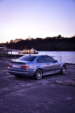
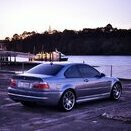
Far out, nearly 14 months since the last update! Well not a lot of progress has been made on the car in the last year. My son deteriorated quite quickly from the start of last year, to the point that by June he was a long term admission to Starship. He had his liver transplant on the 24th September (I was the donor), and he was home 9 days later (a record). It’s totally changed our lives. The last few months have been spent recovering (for me) and getting our lives in order. Last week I cleaned the car, did oil and filter change and this last weekend my wife and I did a day trip to Coromandel for my wife’s Granny’s 80th. We took the long way round (via Clevedon and Miranda) and had a great time. Few photos from the trip attached.
-
Appreciate it's not going to be quick enough for you to get by the 20th, but as a backup option there are a couple of sets on the to BMW Parts For Sale Or Swap UK Facebook page. Being a UK page they'll be RHD sets. Cheers, Matt
-
I don't think that "S2BA BMW LA Wheel Double Spoke 88" refers to something different to the "standard" style 88's. If you have a look at the below that's the exact description applied to the style 88. S2BA is just the option code that describes the style 88's. http://bmwfans.info/parts-catalog/E46-Sedan/Europe/318i-M43/sep1998/browse/wheels/bmw_la_wheel_double_spoke_88/
-
Totally got the context wrong when I first read this ?
-
Hiya, Having done the VANOS myself I would say that the most complex/fiddly part of the whole exercise is getting the position/timing right when re-attaching the VANOS unit. I point that out, because if you purchase a whole replacement unit from Dr VANOS or similar and plan to install it yourself it's worth pointing out that the installation isn't a complete walk in the park (I'd argue that reinstalling the unit is more complex than the disassembly and rebuild of the unit). Good luck with figuring out the best option ?
-
I went Koni Yellows with stock springs, didn't want to really lower the car given NZ's roads. The Koni Yellow's at full soft are equivalent to OE. I've firmed mine up slightly and am very happy with the setup.
-
Every time I see a new post in this thread I hope it's me that's been spotted. Then I remember I never drive it ?
-
They're not Style 359. 359 have 8 segments and those have 7...
-
Yeah there's quite a lot of evidence on overseas forums that would suggest that it's prudent to replace rod bearings at 100,000mi/160,000km. Not all cars need them replaced at this mileage, but there are enough that do that make it not worth the risk to not. I replaced mine at 140k and I'm glad I didn't wait any longer. Yep completely agree that if you're buying an E46 M3 you need to be budgeting for more than the cost of the car. Can confirm from first hand experience that your $35k total figure is pretty accurate ?
-
E46 M3 GTR breaking a lap record narrated by Stuck
Karter16 replied to LemonHunter's topic in Videos & Sound
Man what a great video! -
At the risk of being told again that I'm being too harsh about this car I think that the following probably counts against it. 1: Being a UK import it would need to be checked very carefully for rust. A quick watch of Redish Motorsports Youtube channel shows what salt on roads does to cars. 2: At 170k it will need the rod bearings done. 3: As above it likely also needs VANOS done. 4: I know that in the Q&As the owner says that the shops its been in haven't raised any RACP issues, but unless you drop the subframe and clean the RACP and inspect it in detail you don't actually know what condition your subframe is in. Unless you know your E46M3s you wouldn't really know that the CS was "special". If you did then you'd probably be concerned about the above things. I'm surprised at the number of comments about the Imola red interior counting against it. I think the red interior is pretty cool, but I realise that's completely personal preference. I think probably the fact that it's a CS is offset by the mileage and the fact it's a UK import. I think it would be a cool car for the right person who was willing to spend some money on it/had checked carefully what they were getting into. Certainly a pretty special spec to own in NZ.
-
Yeah quite possibly I am - that's why I posted to see what everyone else thought. Don't see a CS come up very often in NZ so was genuinely interested to get peoples' thoughts and impressions ? Didn't mean to come across as negative or picky - although re-reading my post I can see why it came across that way. There's a wide range of asking prices for E46 M3's of various conditions on the market, this one is a bit special being the CS so I was interested to see how people interpreted that against the asking price and the condition/mileage of the car. Cheers for your input ?
-
173km, $35k buy now. Subframe not inspected or addressed and VANOS not done. Rod bearings are surely well on their way out at that mileage as well. The 'CS' badge is surely a bit of a drawcard, although not sure if that's offset by the fact it's an import??? If it's a UK import, which I think it must be if it's a CS?, then there's underbody rust, etc. to possibly worry about. https://www.trademe.co.nz/motors/used-cars/bmw/auction-1903106984.htm?rsqid=0132df325a1c421cb268290aebf785da
-
Yeah that is exactly what we did with some friends a few years ago. The coast road has some great scenery. The bridge where the scene in "Boy" was filmed is pretty scenic, and the lighthouse is worth a trip as well. As you say the wharves are good fun to visit as well.
-
Yeah they're a weird design. Seems like you should be able to slide them off the rails, but you can't. I was actually tricked by the first one I did in that it popped off relatively easily. The second one took a lot more time and careful attention to get off!
-
Update #25 The last week I've found an hour here and there to get a bit more done on cleaning the car up. I've removed the wipers, windshield cowling and side repeaters, and done a preliminary clean up. Today I had a couple of hours and removed the rear lights to clean them up. Everything was super filthy from all the pine pollen that's accumulated on the car. I've done a preliminary clean on the shell around where the lights mount. They'll get a second deep clean in a little while. I then got stuck into cleaning the tail light enclosures up. I removed the foam rubber seals and the black trim pieces so I could clean everything up properly. Some time spent with soap and warm water, a toothbrush and a cloth and they cleaned up very nicely. The foam rubber seals are still soft and in great condition - they've lasted well considering they're 13 years old. While the boot is disassembled I'll take the opportunity to go through and remove the extra wiring that was added when a previous owner had a tow bar on the car... Til next time.
-
Congratulations - look forward to seeing some photos!
-
Don't forget to check whether your vehicle has previously had the structural epoxy (foam) applied (BMW did the rear mounts as part of a service bulletin) before welding. You wouldn't want to be welding onto the RACP anywhere structural epoxy has previously been inserted. Bummer that your car has cracks, but not really that surprising. Fortunately it's a well known issue and there's lots of info out there about how to best address. Hope you can get it sorted out!
-
Congratulations - Imola Red is a beautiful interior colour. Hope the checks all go well - looking forward to following your progress!
-
Update #24 Last night I did a quick test of cleaning auto wax, dirt, etc. off the black trim on the boot handle mechanism. Before: To clean I simply used hot water with some regular liquid hand soap in it and I carefully scrubbed the black plastic parts with a toothbrush. The heat and soap helps soften and lift the wax. I then used a cotton cloth soaked in the hot water and soap to wipe away the remaining wax. Had to go over a few spots a second time, but I'm really pleased with how well this has cleaned up. After: I've got lots more to clean, and I want to go through and remove the extra wiring from when the first owner of the car had a tow bar installed. I'm also still trying to decide whether I attempt to restore the surface of the reversing light enclosures or whether I just buy new ones. Looking at them it looks as though the plastic may be started to fracture and degrade beyond the surface layer, so may just be better to buy new ones. I've also got a couple of bits and pieces on order from Milland for the front of the car, so I'll update when they arrive.