wrs
-
Content Count
348 -
Joined
-
Last visited
-
Days Won
2
Everything posted by wrs
-
Thanks for the info. This morning I replaced the A1 radiator with a new standard BMW one from Silverdale. First I flushed 30L of distilled water through the engine. It was refilled with a generic inhibitor and distilled water. Further investigation has come up with some interesting results: Exp = Expansion tank to engine earth (E36 M3 style expansion tank mounted near the firewall) Rad = Radiator Core to engine earth Cur = the current flowing if radiator core shorted to the engine earth Cold just after filling: Exp -100mV, Rad -1020mV, Cur -0.2mA Hot Idle (92'C): Exp -152mV, Rad -1005mV, Cur -2.4mA Hot 3000RPM (95'C, thermostat open, cooling fan running): -1060mV, Cur -2.5mA Hot Idle (92'C) Headlights on: Exp -155mV, Rad -1005mV, Cur -2.4mA Cranking (92'C): Exp -154mV, Rad -1025mV, Cur -2.4mA Combination of any electrical loads (headlights, brake lights, heater, windows): Exp -150mV to -156mV, Rad -1005mV to -1025mV, Cur -2.4mA to -2.5mA Battery earth disconnected (92'C): Exp -152mV, Rad -1005mV, Cur -2.4mA It appears it's not bad earthing or significant change would be seen with loads and cranking. Also, since the radiator is fully insulated from the chassis it's electrically floating and has no current path to the engine earth or chassis. The inlet and outlet pipes both connect to the same aluminum housing so both hoses are at the same potential where they connect to the engine. For there to be a -1V difference between the radiator core and the engine earth there has to be galvanic corrosion occurring. Maybe the generic inhibitor I've used is rubbish and is creating a reaction? So, how to fix this. If the coolant was truly inert and non-conductive then there would be no voltage from the radiator core to the engine earth. How to fix this is unknown, any ideas?
-
If you put M3 Evo headers, M3 Evo full exhaust, Link ECU and bored throttle body on it you should get over 300 from it. Got 298hp/220kW/344Nm from my M50B30 with this configuration, M52B32 might get more. If nobody wants it I'd be interested in the M Power cover!!
-
Does the purple rack have slightly more overall travel than the standard E36 rack? I recently failed a warrant because a new anal guy at VTNZ noticed 2 tiny rub marks on my inner guards where the wheels just rub slightly from time to time (20mm mark in the underseal but no metal exposed). I'm sure it didn't do this prior to the purple rack. I had to pop the boots and put a 3mm spacer on each rack shaft end to reduce the travel - once done there was no issue with the warrant.
-
Hoping someone can help with what has become an ongoing problem. I installed an all ally radiator when I did my engine swap around 5 years ago. The first all Ally radiator lasted about 3 years and failed round the core tubes. The second lasted 1.5 years and the latest really expensive one from A1 Automotive Cooling has lasted 6 months. All have failed round the core tubes. The first radiator showed no signs of electrolysis. The second and third did though, black on the inlet tank side and brown on the outlet tank side. In all cases I've used distilled water 50%, BMW blue coolant 45% and Redline water wetter 5%. In between radiator replacements I've done a flush with distilled water. On the last replacement with the A1 radiator I measured voltages on the expansion tank and from the radiator metal to the engine earth. The expansion tank to engine voltage was -1.0mV ad the radiator metal to engine block was -600mV. All documentation I've found says to measure from the liquid in the expansion tank to engine earth and if this is very low (-1.0mV is pretty low) then everything should be ok. In my case it hasn't been ok. The problem with the E36 M3 expansion tank setup is it's remotely mounted near the firewall. The only flooded connection through a hose is to the back of the head. The hose from the top of the radiator inlet side to the expansion tank isn't flooded with the engine off the therefore there won't be any electrical connection/conduction if the coolant is ionic in any way. How therefore can I check the system to make sure electrolysis won't be an issue? I suspect the -600mV from the radiator metal to engine earth is the problem. The radiator is well insulated from any metal and is isolated from the engine earth at all times. Even applying significant force in every direction to the radiator does not make the radiator move enough to touch ground metal. I would have though -600mV is ok as long as the coolant is non-conductive as there will be no current flow to create and electrolytic reaction. I'm at a loss to what to do and don't know what is or isn't an acceptable voltage and where the acceptable voltage should be from too. The usual guidelines for measuring the coolant voltage in the expansion tank to engine earth obviously don't work in my configuration. So, how to solve this ongoing problem - any ideas?
-
Thanks, was a long project with a few changes along the way (as I learned what did and didn't work). I don't have any photo's of the internal matrix (anymore) and have never seen inside the B&W speakers. I did pinch their idea though as it makes perfect sense and suspect the insides would be similar. I'll take some pics of the amps later on. They're not painted yet - just white primer. I don't think I've got any pics of the insides though - maybe the input board only. I'm thinking about changing the amps to Hypex so they can be mounted into the base of the speakers. There's room left in the base for amps to go, I just never did it. With the Hypex amps and Power Supplies it would tidy up the wiring a fair bit. Most stereo setups (2 speakers) only have one pair of speaker cables and interconnects (some maybe 2 pairs of speaker cables). For active setups you need one pair of speaker cables and interconnects per speaker - 5 pairs or each in my case. I like to show it off too so anyone who wants a listen is welcome if they're ever in Napier. The next generation will have the amps, and DSP in the speaker with wireless connections. All I have to do is figure out how to sync the two speakers. It shouldn't be too difficult... The only unknown is how sensitive the ear is to left/right timing errors - I suspect as long as the difference is under 1us you won't notice. It should be fairly easy to get the two speakers sync'd to under 100ns. Here's some amps pic's: Front: Still only undercoated... The indicators show power, protection, overtemp and clipping. These pre-date the DSP modelling the speakers and amps so clipping cannot occur. Protect can still occur if there's DC present in the output. Overtemp is in case of fan failure. There's 2 internal low speed high-pressure fans that suck air in over the 5 x 1kVA toroidal transformers , 200,000uF caps per channel and then blows up the heatshink. The fans are variable speed based on heatsink temp and you never hear them unless I've been blasting Infected Mushroom for 20 minutes+ and then only slightly between tracks. Back: Balanced XLR's and 4 Pole Speakon connectors. Balanced Input Board:
-
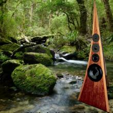
Here's a few photo's of bits of the system: Main Speaker: The speaker is 1.8m tall and has no parallel sides + the sides are curved and taper in thickness - no standing waves or resonances are present due to every panel being irregular in shape and thickness. There's an internal matrix to add extra stiffness and create tunnels to absorb all rear speaker radiation by packing the tunnels with progressively dense absorption material. Sub: Above the sub is a 55" TV to give some idea of size - it weighs 330kg. The sub also has an internal matrix to stiffen the sides, top and bottom. The matrix is on 100mm x 100mm centers. It's a stereo sub with a separation down the middle with each half having 2 x 18" driver. Because it's 4th order bandpass you only see the port for each channel. DSP Processor: The DSP is an Analog Devices ADSP21469. There's an Intel NUC PC included as a media player using J-River. The DAC's are PCM1794A with AD797 V/I converters and LT1028 LPF in a balanced non-earth filter arrangement. The volume controls are PGA4311, again balanced with no earth. The 10 x DAC outputs are balanced 600 Ohm. Interconnects are Mogami Starquad into a 600 Ohms balanced input on the amp per channel. The V/I and filter Opamps, R's and C's are under the black heatsink as they run quite high bias and need forced cooling. There's some squishy thermal pad between the heatsink and components. The sound card is a M2Tech HiFace modified with analogue supplies to reduce jitter and the I²S signals are directly tapped off USB chip to the DSP so there's no conversion to SPDIF and back. Power Supply: The amps are: Tweeter: 350W Mosfet 8 Ohms Mid: 350W Mosfet 8 Ohms Lower Mid: 700W Mosfet 4 Ohms Bass: 1250W Mosfet 4 Ohms Sub: 2500W Mosfet 2 Ohms The reason the amps are so big isn't to make the system loud - it's to have 2x the voltage required to apply speaker correction to properly control cone movement and overcome the voice-coil inductance.
-
Yeah, a progress update would be good. If I'd seen this a few years ago when started I would have suggested what I've written below. Considering improving the factory system in my E36... I'd second going active as it's the best and really the only way to get a fast dynamic response. It also opens up the possibility to properly add DSP based correction and active crossovers to the system. I'm not sure if pre-amp level programmable DSP based crossovers are available with FIR capability for the car audio market. You need something you can add your own FIR coefficients to and it must have programmable delays. With a decent DSP system you can get amazing results. I also second Morel. These guys make amazing drivers with most of the design engineers ex Dynaudio. Most of their older drivers look exactly like Dynaudio... I started a home audio project back in 99 which was completed about 3 years ago. It's a 5-way active system with a sub and 2 x 4-way towers. The sub uses 2 x RCF L18P200KN drivers in an isobaric 4th order bandpass tuned for bandwidth, not peak. This puts the -3dB points at 13Hz and 90Hz with 0.7dB ripple in the passband. With 2 of these I can easily achieve 120dBA at 20Hz. The crossover points are 70, 280, 1120 & 4480 Hz, all 80dB/oct FIR with under 0.1dB pre-ringing and the highest peak in the stop-band -96dB. The bass driver is Morel Ultimo 124 car sub which has typically 0.1% distortion across the frequency range it's used in (70-280Hz @ 95dBA). The lower-mid is Dynaudio 15W75, Mid Dynaudio Esotar M560D and Tweeter Dynaudio T330D. All drivers can peak at 120dBA without compression. Another thing you can do if you get a programmable DSP is perform partial transfer function correction of the drivers. You measure the driver transient response which shows you the mathematical relationship between the electrical signal and what the driver does. You then invert this, apply a low-pass filter to the result (so you don't need infinite power) and apply it to the DSP. Think of the speaker cone a block of concrete and the voice-coil inductance as a spring attached to the block of concrete. If you instantly push the back of the spring in 100mm and hold it then instantaneously the concrete does nothing. It then begins to accelerate due to the force from the spring. It eventually reaches the 100mm point but because it now has momentum it over shoots and keeps going. The force from the spring now inverts and start to pull the block back. The end result is the block bounces around on the spring for a while slowly diminishing until it eventually settles at 100mm from where it started. The same thing happens to speaker cones. Using the DSP you can almost completely remove this damped ringing to compensate for the physical limitations of the driver. Another cool thing you can do with the DSP is add thermal modelling for the voice coils and excursion modelling for the cones to limit the system so it never operates outside the maximums. Lastly, you can do room correction with the DSP box (if it has enough processing power). A lot of DSP based room correction is done using FIR but I find this destroys the sound stage and makes the music sound dead. This is possibly because FIR cannot fix the decayed ringing natural room reflections produce - they target the first reflection well but often don't address the ringing. Instead I use IIR based parametric EQ which behaves the same way natural ringing does. It preserves the soundstage while allowing the room to be corrected to within 0.5dB. You might need up to 40 bands per channel to get a good response though - depending on the room. You may not need this many bands in a car. The end result is a system that's very fast, has very low distortion, near-perfect timing, amazing imaging and sounds natural (like live music). It also adds very little of it's own character to the sound which some people don't like as they're used to hearing the distortion most speakers add - sometimes this can even be quite pleasant). I built my own DSP processor with 10 output DAC's as nothing was available commercially with features I needed when I started the project. Most likely something is available now for car audio with many/most of these features. You could also partially DIY a DSP box using parts and software from MiniDSP. Of course, this might also be outside your budget...
-
Did a manual conversion in my E36. Had to add hoops for the cert guy. Seems to be a grey area, some certifiers want hoops and some don't. Also, if it was done after Nov 2017 and the brake pedal was changed to add the clutch pedal it will need certifying ( that's if they notice it was converted at the testing station). The tunnel on E36/E46 is really tight with not much room for hoops. You'll have to go custom for the rear hoop as the ready made ones don't fit. Ready made might fit the front but they're butt-ugly... The trans tunnel is also double skinned on the E36 - not sure about the E46. If the E46 is double skinned and you plan to put the hoop bolts through the tunnel side walls they'll need crush tubes welded in. You'll also need to lift the carpet...
-
Sorry, already gone-burgers...
-
Purchased the wrong kits - was rushing to get the order done while at work and got M3 versions by mistake, don't have M3 half-shafts (duh)!! Purchased from Bimmerworld: http://www.bimmerworld.com/Driveline-Shifter/Differentials-Accessories/CV-Boot-Repair-Kit-Inner-33-21-7-840-673.html ($24.99 USD ea) http://www.bimmerworld.com/Driveline-Shifter/Differentials-Accessories/CV-Boot-Repair-Kit-33-21-9-067-806.html ($21.99 USD ea) This is for 2 x Inner and 2 x Outer kits including grease and bands. Paid $153.64 USD all up inc freight. Time for a bargain, will sell the lot for $100 NZD + freight Anyone interested?
-
Unfortunately we don't do much for AT - too bureaucratic to deal with anyway. There is a project in the pipeline for AT that might solve this problem anyway (if it goes ahead).
-
Just checked, we're out of boards. I need to order some more and they only take about a week to arrive. The PCB uses a CD40106 Hex Schmitt Inverter chip and simple R's & C's to create delays and sequence a pulse onto the relay coil. The relay contacts are isolated which make it universal to use. If you're interested I can make one up and send it to you. The parts cost is about $10... It has 4 wires. Red is +12V, black is ground. The two White wires go to the relay contact. It makes it really simple to install. The hardest part will be finding the 12V supply and routing the wires behind the dashboard.
-
Looked up on Youtube - looks like a simple button press for a specific time. It should be quite easy to add a small timer board with a relay output to emulate the normal press function of the button. We make a board for turning on TV's automatically for the bus industry which waits a programmable time then emulate pressing the on button for a programmable time. It work fine on 12V and could easily be used for your application. You need to find a 12V source that's active while running and take the 2 relay contact wire to the DTC button contacts.
-
How do you switch modes usually (button)? If it's a simple button press then you could emulate pressing the button using a relay that closes momentarily after a short delay.
-

Setting up a VM for ISTA+ and ISTA-P and other tools
wrs replied to Driftit's topic in General Discussion
Yeah, download the VM image onto a USB stick and plug it in when you need it... I've got some VM experience with ESXi but not enough to even think about attempting this - can see hours and hours disappearing... -
Setting up a VM for ISTA+ and ISTA-P and other tools
wrs replied to Driftit's topic in General Discussion
Yep, nightmare!!!! Could also mean a VM on a USB stick... -
Setting up a VM for ISTA+ and ISTA-P and other tools
wrs replied to Driftit's topic in General Discussion
Maybe he means a cloud VM for everyone to share?? -
Neither can I. If you right click on the 'image preview' and select view image you get '440 login timeout'. I suspect you used links to a 'non-public' folder or used img tags that are for private viewing only. Try loging out of your image hosting website and reloading this page to see if you can still see the images.
-
If they were for a manual I'd be in...
-
I have one about 4 years old in pretty reasonable condition, still has the level switch. Recently upgraded to the M3 style expansion tank so no need for it. Yours for $10 + freight.
-
At that price, helps me justify what I've spent on my conversion... Of course, not a genuine M3 but $38K!!! Did a full repaint on mine in Feb/Mar - I was 50/50 between this colour and factory original. I really like this colour!! Ended up going with the factory original colour of Mauritius Blue but it was close...
-
@3pedals, totally agree - I'm now sure the engine mounts needed to be changed at the same time. However, even if they were I'm sure the overall noise still would have been too much. I further suspect that when changing to aftermarket engine and/or gearbox mounts it's important to match the two to make sure they have the correct characteristics so they don't fight each other. @zero, I don't think the torque would have had anything to do with the problem in this case even if it was wrong. The mounts have a plate and stud bonded to each side with a solid rubber/urethane combo in between - essentially a copy of the OE mount with more and stiffer rubber with a small cup on one side. It's not like a bush with a bolt through it that's been squished too much due to too much torque. In the case of the mounts in question, you could likely torque them up until they almost stripped and it would make zero difference to the level of vibration. They were not over-torqued anyway and it was easy to undo the nuts when I removed them. With the new OE mounts I did torque them up quite tight - much tighter than the Ruff ones and have no problem with any vibration or noise issues.
-
The fixing on each side is a stud similar to the OE mount. I doubt overtightening would be the problem. They have a special semi locknut so don't need to be very tight.
-
Not the biggest hit I've had on the road to learning. I took the guys at SpeedFactor at their word when the said they wouldn't be much louder than the OE ones - maybe they didn't really know. When I rang them to comment about the noise level increase they did say the noise coupling might have been worse because the engine mounts weren't changed to stiffer types at the same time meaning all the vibration was transferred into the trans tunnel instead of distributed across the whole front of the chassis. Even so, I suspect they still would have been much too noisy for most people unless they were building a track car.
-
Thanks for the heads-up. Have remote locking/unlocking with the alarm so having a different key wouldn't be too big a pain.